 Skip to main content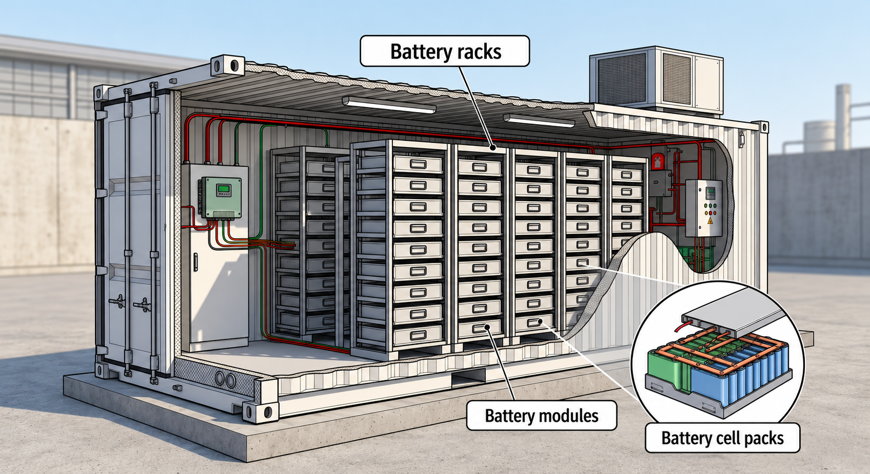
For decades, the power system operated in a relatively straightforward way. On one side were utility-scale electricity generators – power plants and combined heat and power plants of various types and sizes – and on the other were consumers, also of various types, from large industrial plants through medium-sized industry and large commercial, office and hotel facilities to individual consumers and households. Most power plants and CHP plants were conventional facilities, powered by energy generated through the combustion of fossil fuels. As long as CO2 emissions were not strictly monitored, fuel stores at these plants were full. There were also no other significant technical barriers, so their output was very stable and predictable. The energy equation was simple: electricity generation met the immediate need for consumption – generation = consumption.
One side of the energy equation generated and sold electricity in a stable and predictable manner, while the other consumed and purchased it somewhat less steadily, but still quite predictably. Generators and transmission system operators carried the full responsibility for ensuring stable system operation by maintaining the balance between supply and demand. Most of the time this worked, although sometimes it did not, hence the “power supply restriction levels” known from older films and publications, when generators were unable to keep up with the needs of large consumers and had to persuade them to reduce their demand.
According to the Institute of Environmental Protection, in 1990 electricity generation in Poland came from:
- coal: approximately 76.8%,
- oil: 14.8%,
- natural gas: 8.9%,
- biofuels and renewable energy sources: 3.9%.

Figure 1. Balance in the historical power system – generation balances consumption. Figure generated using artificial intelligence.
Today the situation is completely different, as can be seen from the profiles and types of electricity generators reported for August 2026 by the PSE portal. (Polish Power Grid Company portal – system data, viewed on August 26, 2026, rounded to one decimal place.)
- Coal, oil and gas combined: 42.4%
- Hydropower plants: 0.3%
- Onshore wind farms: 4.3%
- Offshore wind farms: 0.2%
- Photovoltaics: 52.8%
It is not only the generation profile that has changed. Consumer behaviour has also changed significantly, with many consumers becoming local generators themselves – producer + consumer = prosumer – and energy now flowing in different directions rather than only from generators to consumers.
The system has grown, the number of sources has increased, and their nature has become less stable. The behaviour of wind and photovoltaic power plants can be forecast when good weather forecasts are available, but it is also obvious that photovoltaic installations will not generate electricity after sunset, while on bright, windless days wind farms cannot be relied upon. In this situation, maintaining the balance between supply and demand, and consequently ensuring stable system operation, becomes much more difficult.

Figure 2. A fragile balance in a complex energy market. Figure generated using artificial intelligence.
When trying to balance supply and demand in a market, a good storage facility can be extremely useful. If a farmer produces too many apples and has no immediate buyer, they look for a good warehouse where the apples can be stored until demand increases. This way, the farmer does not lose either the product or the money. When a customer decides they want apples, the apples are still available. Of course, storage comes at a cost.
The energy market works in a similar way. There are storage systems designed for electrical energy, and energy can be stored in many different ways:
- in potential energy, for example by lifting a large weight when there is excess energy and lowering it to generate energy when there is a shortage; often that weight is water, as in pumped-storage power plants,
- in kinetic energy, by accelerating a mass when there is excess energy and then recovering that energy by slowing it down; this is how kinetic energy storage systems, also known as flywheels, operate,
- in a certain sense, energy can also be stored by heating a material, although converting it back into electricity later is difficult,
- in the energy of chemical bonds, either in elements such as hydrogen and fuel cells, or, much more commonly, in components known as batteries.
This last mechanism is the most widespread. For years, we have stored electricity this way to start vehicles using batteries, although some of us may still remember manual starters in motorcycles and cars, as well as to power portable devices, from torches, calculators and radios to today’s smartphones, tablets, watches, headphones and portable speakers. Since around 2009, with the first generation Nissan Leaf, batteries have also been used to power electric vehicles, today covering almost every type of vehicle, from passenger cars and vans to buses, lorries and specialist vehicles. Batteries and accumulators vary and are based on different electrochemical processes and material technologies. Lead-acid batteries remain the most widespread and, in various forms, still dominate in applications such as cars. However, it is now widely understood that other technologies dominate portable devices and electric vehicles because of their much better energy-storage capacity relative to size and weight. These include NMC and LFP, while Na-ion and solid-state electrolyte technologies are increasingly being discussed.
Over the past decade, batteries have significantly improved their technological parameters, including the number of charging cycles, thermal characteristics and availability in different forms and shapes. At the same time, their prices have steadily fallen, making them an attractive alternative for building large systems capable of operating together with power systems.

Figure 3. Energy storage systems supporting stability in a complex energy market. Figure generated using artificial intelligence.
It is not difficult to see how such an energy storage system can greatly support grid stability. Put simply, it can quickly absorb excess energy by charging, and when the system is short of energy, it can discharge it. In our example with the scales shown in the figure above, it acts as a kind of shock absorber, both for generators and consumers. As a result, operators and participants in the electricity market gain a new tool: a Battery Energy Storage System, or BESS.
What is BESS really?
As the name suggests, a BESS is a system, not a single device or even simply a collection of devices. There is no single market standard for the construction of a BESS, but these installations, often referred to as battery parks, have many common components. Depending on the design, these may differ in power, appearance, location and role.
Let us begin with the simplified arrangement shown in the figure below.

Figure 4. Simplified BESS park. Figure generated using artificial intelligence.
The main components of most BESS parks are containers. These usually contain battery modules installed in battery racks. The modules often resemble slide-in cartridges with electrical and communication terminals on the front panel.
Inside are battery cell packs and a BMS, or Battery Management System, responsible for managing and protecting the local pack and communicating with the outside world. It is worth becoming familiar with this terminology, because the terms rack, module and cell are often confused or used interchangeably, which can lead to misunderstandings. Packs inside modules, as well as the modules themselves, are connected in series and in parallel to achieve the required output voltage and total current.

Figure 5. Container, rack, module and cell – terminology used in battery systems. Figure generated using artificial intelligence.
Batteries are components that store direct-current energy. A typical cylindrical household battery, just like a battery module, has clearly marked positive and negative terminals – direct current, or DC. The power grid, on the other hand, uses alternating current – a sinusoidally varying current, or AC. To connect the two, a device is needed to convert the positive-negative DC supply into a 50 Hz sine wave. This is the role of PCS, or Power Conversion Systems. During charging, such a power electronic converter draws energy from the three-phase AC grid and, operating as a controlled rectifier, uses it to charge the cells in the modules. When the battery is discharging, the process is reversed. The system draws direct current from the battery and converts it into alternating current while operating as an inverter. From a technical perspective, this is a four-quadrant power electronic converter.
In modern converters, power quality on both the DC and AC sides is very high, and converter efficiency often exceeds 98%. Typically, a single PCS serves an entire group of battery modules. The next step is to combine the energy from individual PCUs into larger groups and match the output voltages of the inverters to the voltage levels typically used in the power system in a given region. A typical PCU is therefore followed by a transformer, often with two primary windings to which between one and several PCUs are connected. The secondary sides of these transformers are connected to switchgear, often at medium voltage. This is an old but still commonly used term; in Poland, typical voltage levels are 15 kV and 20 kV. Depending on the system capacity, this transformer will be connected through switchgear to the local power grid or, in the case of large BESS parks, the voltage level will be increased once again using a high-voltage transformer.
Naturally, measuring equipment and systems are present at many points throughout this complex installation, on both the DC and AC sides. There are also electricity meters between the park and the power grid for final settlement purposes. The park is supplemented by several additional systems. A significant role in the park’s internal energy balance is played by the heating, ventilation and air conditioning system, or HVAC.
Batteries heat up during intensive operation, as every smartphone owner knows. As a result, battery modules require cooling on hot days. On the other hand, batteries cannot operate, particularly at full power, at very low temperatures and therefore require heating. These requirements are handled by the park’s HVAC system, which can reach an impressive scale and require substantial amounts of power. Safety systems are also required, covering both electrical safety, with numerous protection systems of different types at various points within the BESS park, and fire protection. Different manufacturers use different technologies, but installations include numerous sensors for smoke, fire and temperature, as well as fire suppression systems and fire barriers. Technical spacing is also maintained, both for internal logistics, since these are neither lightweight nor easy-to-transport components, and for safety reasons, as well as to provide easy access to key components within the park. As can easily be imagined, such a facility generates enormous amounts of data: measurement data, communications data, information about equipment status and condition, and a very large number of electrical measurements. Managing such a complex system is a highly responsible and demanding task, which makes having a trusted partner particularly important. At park level, management is handled by park controllers, which often perform the role of an EMS, or Energy Management System, which we discuss in a separate article.
A well-designed and properly managed BESS requires not only the right technology, but also a partner capable of combining power engineering, automation, data and IT systems into a single functioning ecosystem. At ConnectPoint, we deliver projects of a similar nature and, based on our international experience, we see enormous potential in the management of BESS systems.
